Aegis Earth BunkersAegisEarth Bunkers
Book Private Consultation
Engineering technical room

Systems Brief

Engineering systems behind every Aegis bunker.

Seven independent, deeply engineered subsystems — each designed for long-duration autonomy, low maintenance, and graceful degradation. Below: the schematics, the specifications, and the reasoning behind each one.

01System

Structure & Shell

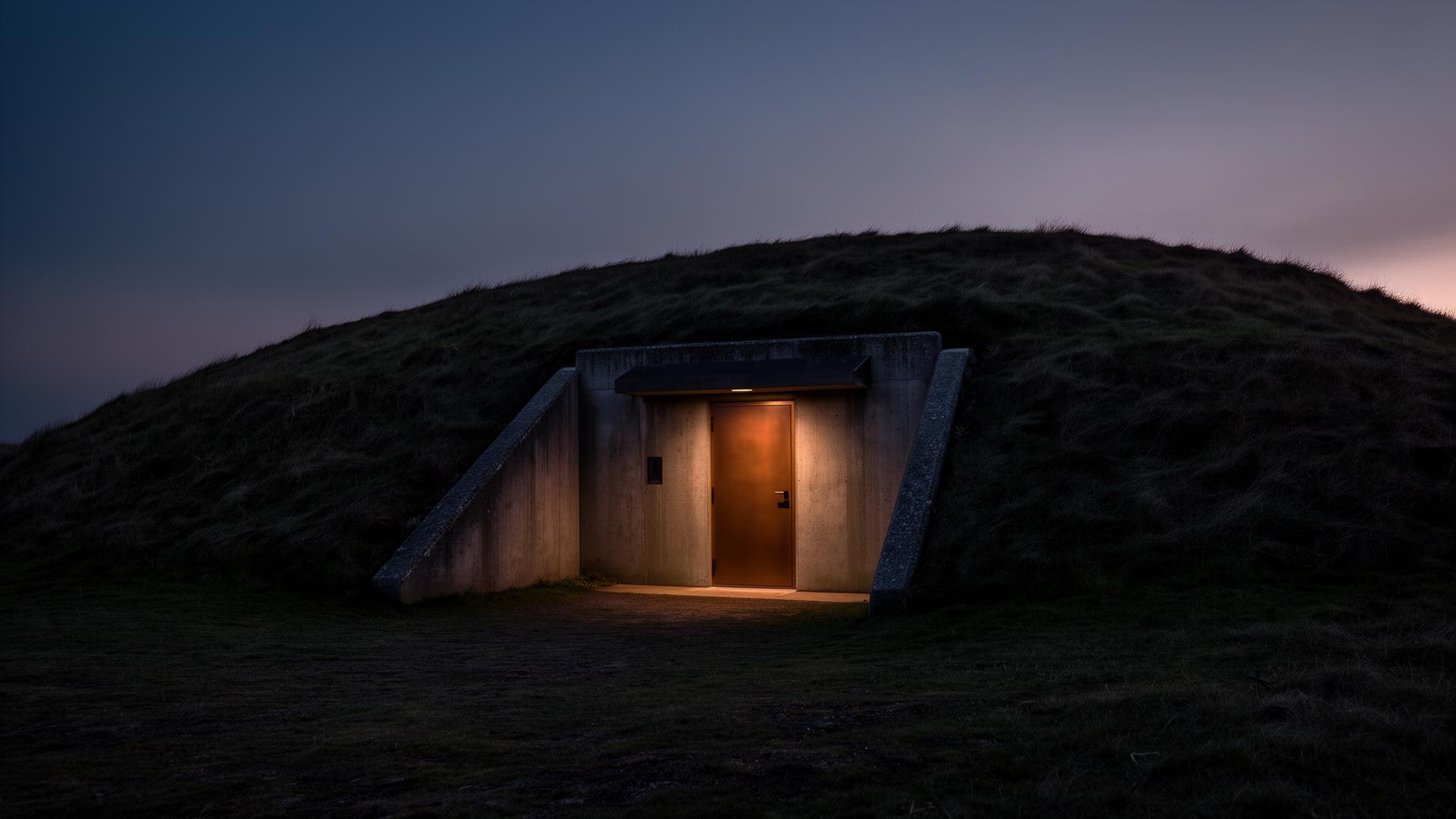
Reinforced underground envelope with full waterproofing.

The shell is the foundation of every life-safety guarantee in an Aegis bunker. It is a reinforced concrete monolith — typically 300–450 mm walls and roof slab — cast against engineered formwork with a continuous double rebar cage and waterstop joints at every cold pour.

Above the structural concrete sits a layered waterproofing strategy: a primary bonded membrane in direct contact with the slab, an air-gap drainage composite, and a secondary geotextile-protected sheet against the soil face. Perimeter French drains route groundwater to a sealed sump with redundant pumps.

Earth cover (typically 1.2–3.0 m) provides ballistic, thermal and acoustic mass. The envelope is designed for sustained overpressure events and is independently verified against project-specific loading from soils, hydrostatic pressure, and surface activity above.

Subsystems

  • Reinforced concrete monocoque, 300–450 mm
  • Continuous double rebar cage with waterstops
  • Primary bonded waterproof membrane
  • Air-gap drainage composite
  • Secondary geotextile-protected sheet
  • Perimeter French drains and redundant sump
  • 1.2–3.0 m engineered earth cover

Indicative Specifications

Wall thickness
300–450 mm RC
Concrete grade
C40/50 typical
Waterproofing
3-layer system
Earth cover
1.2–3.0 m
Design life
100+ years
Schematic / 01Not to scale
02System

Air Management

Filtered, monitored, multi-mode ventilation.

Air is the most time-sensitive resource in any sealed environment. The system runs in three operational modes — Open, Filtered, and Sealed — and transitions between them automatically based on outside-air sensors and interior CO₂ readings.

In Filtered mode, intake air is drawn through a coarse pre-filter, a HEPA H14 stage, and a deep-bed activated carbon column rated for CBRN-class chemical and radiological particulates. Differential pressure transducers across each filter bank predict cartridge life and trigger service alerts well before breakthrough.

Sealed mode isolates the envelope entirely. Interior air is recirculated through a CO₂ scrubber and a molecular-sieve oxygen concentrator. Positive overpressure (typically +50 Pa) is maintained at all times in Filtered mode to prevent infiltration through any unintended breach.

Subsystems

  • 3-mode operation: Open / Filtered / Sealed
  • Coarse pre-filter + HEPA H14
  • Deep-bed activated carbon (CBRN-class)
  • Differential-pressure cartridge monitoring
  • Molecular-sieve O₂ concentrator (sealed mode)
  • CO₂ scrubber loop
  • +50 Pa interior overpressure

Indicative Specifications

Filtration
HEPA H14 + Carbon
Air change rate
4–6 ACH
Overpressure
+50 Pa
Sealed endurance
72+ hrs (configurable)
CO₂ alarm
> 1000 ppm
Schematic / 02Not to scale
03System

Water

Stored, purified, monitored.

Potable water is held in food-grade polyethylene cisterns sized to the household and autonomy target — typically 3,000 to 15,000 litres. Tanks are isolated from sunlight, vented through carbon-filtered breathers, and circulated through a UV maintenance loop to prevent biological growth during long dormancy.

Raw water from a borehole, rainwater catchment, or external delivery passes through a five-stage purification train: sediment filter (5 µm), carbon block, reverse osmosis membrane, UV-C steriliser, and a remineralisation cartridge that restores taste and pH balance.

All flow, pressure, turbidity, TDS and UV-lamp health is logged continuously. The system can run end-to-end on battery power and can be configured with triple redundancy on the purification train for mission-critical deployments.

Subsystems

  • Food-grade PE storage, 3,000–15,000 L
  • Carbon-filtered tank breathers
  • UV maintenance recirculation loop
  • 5 µm sediment + carbon block pre-filter
  • Reverse osmosis membrane
  • UV-C steriliser
  • Remineralisation cartridge
  • Continuous TDS / turbidity / flow logging

Indicative Specifications

Storage
3,000–15,000 L
Purification stages
5
RO recovery
~50%
UV dose
≥ 40 mJ/cm²
Daily output
Up to 600 L/day
Schematic / 03Not to scale
04System

Energy

Solar PV, battery storage, full off-grid capability.

Energy is delivered by a solar-first hybrid architecture. A roof- or canopy-mounted PV array (typically 6–20 kWp) feeds a hybrid inverter, which simultaneously serves the bunker DC bus, charges a LiFePO₄ battery bank, and exports surplus to the property grid where available.

The LiFePO₄ battery bank — sized for 2 to 7 days of full autonomy — was selected for its thermal stability, deep-cycle longevity and benign failure modes. Each module is individually monitored by a battery management system that reports cell-level voltage, temperature, and state-of-health.

An intelligent load controller prioritises life-safety circuits (air, water, comms, sump pumps) over comfort loads during low-state-of-charge events. An optional diesel or LPG generator provides a final layer of redundancy with auto-start at a configurable battery threshold.

Subsystems

  • 6–20 kWp solar PV array
  • Hybrid inverter with grid passthrough
  • LiFePO₄ battery bank, 2–7 day autonomy
  • Cell-level BMS monitoring
  • Priority-based load controller
  • Optional diesel / LPG generator with auto-start
  • DC sub-bus for life-safety circuits

Indicative Specifications

PV capacity
6–20 kWp
Battery chemistry
LiFePO₄
Autonomy
2–7 days
Inverter
Hybrid, grid-tied
Generator
Optional auto-start
Schematic / 04Not to scale
05System

Sanitation

Closed-loop waste handling.

Sanitation is a closed-loop system designed for long sealed-mode operation. Low-water vacuum-assist fixtures minimise potable consumption and reduce blackwater volume by up to 70% compared with conventional plumbing.

Blackwater is routed through a sealed macerator into a primary holding tank with anaerobic biological treatment. Greywater is separated and passes through a fines filter and biofilm reactor before being recycled to non-potable uses (toilet flush, irrigation) or discharged to a soakaway.

All venting routes through the activated-carbon air column to prevent odour egress in sealed mode. Tank levels, pump cycles and biological process indicators are logged and presented on the central monitoring dashboard.

Subsystems

  • Vacuum-assist low-water fixtures
  • Sealed macerator pump
  • Primary anaerobic holding tank
  • Greywater / blackwater separation
  • Biofilm reactor for greywater reuse
  • Carbon-vented service stack
  • Dashboard-monitored tank levels

Indicative Specifications

Water reduction
Up to 70%
Holding capacity
Sized to autonomy
Greywater reuse
Yes
Odour control
Carbon-vented
Schematic / 05Not to scale
06System

Communications

Resilient, layered, optional.

Communications are deployed in concentric layers so that the loss of any single channel never isolates the bunker. The primary layer is a hardened terrestrial uplink (fibre or fixed-wireless where available), routed through a managed firewall and a local mesh that covers the entire envelope.

The secondary layer is a low-earth-orbit satellite terminal with an automatic failover router. The terminal antenna is integrated into the surface architecture — disguised within roof furniture, garden features or outbuildings — to preserve discretion.

A tertiary HF / VHF radio bench supports off-grid voice and data when all internet infrastructure is unavailable. All three layers feed the same internal network so devices roam transparently between them, and bandwidth is shaped to prioritise life-safety telemetry over user traffic.

Subsystems

  • Hardened terrestrial uplink (fibre / fixed-wireless)
  • Managed firewall + internal mesh
  • LEO satellite terminal with auto-failover
  • Discreet antenna integration
  • HF / VHF radio bench
  • Unified internal network with QoS

Indicative Specifications

Layers
3 (terrestrial / sat / radio)
Failover
Automatic
Antenna
Concealed integration
QoS
Telemetry priority
Schematic / 06Not to scale
07System

Offline AI Knowledge Server

A self-contained local intelligence appliance.

The knowledge server is a fan-cooled, low-power appliance running quantised open-weight language models entirely on local hardware. It is air-gapped by default — no outbound connectivity is required for any of its core functions — and is accessed from any device on the internal mesh.

Its curated library includes medical response protocols, pharmacology references, repair manuals for every system in the bunker, structural and electrical engineering handbooks, agriculture and food preservation guides, legal and continuity documentation, and a curated long-form library.

The appliance can be upgraded over time. New knowledge packs and fresher model weights are delivered on physical media and applied locally so the system remains fully sovereign. Mirrored storage and faster local inference are available as upgrades.

Subsystems

  • Local quantised LLM inference
  • Air-gapped by default
  • Curated knowledge libraries (medical, repair, legal, agri.)
  • Internal mesh access from any device
  • Mirrored storage option
  • Physical-media knowledge & weight updates

Indicative Specifications

Connectivity
Air-gapped (default)
Inference
Local, quantised
Storage
NVMe, mirror option
Updates
Physical media
Schematic / 07Not to scale

Knowledge Continuity

A local intelligence system, designed to retain vital knowledge.

Even when networks are unavailable: medical procedures, repair protocols, continuity manuals, engineering references, and curated survival libraries. Mirrored data, faster local inference, and curated knowledge base upgrades are available.

Discreet bunker entry at dusk

Continuity

Build continuity into the ground beneath you.

Private consultation for clients seeking a discreet, engineered, turnkey resilience asset.